

SBR20A60CT
Introduction
The SBR20A60CT is a diode belonging to the category of Schottky Barrier Rectifiers. This semiconductor device is widely used in various electronic applications due to its unique characteristics and advantages.
Basic Information Overview
- Category: Schottky Barrier Rectifier
- Use: Power rectification in electronic circuits
- Characteristics: Low forward voltage drop, high switching speed, low reverse leakage current
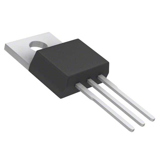
- Package: TO-220AB
- Essence: Efficient power rectification
- Packaging/Quantity: Typically packaged in reels or tubes, quantity varies based on manufacturer
Specifications
- Voltage Rating: 60V
- Average Forward Current: 20A
- Peak Non-Repetitive Surge Current: 200A
- Operating Temperature Range: -65°C to +175°C
- Storage Temperature Range: -65°C to +175°C
Detailed Pin Configuration
The SBR20A60CT typically features three pins: 1. Anode 2. Cathode 3. Gate (for some models)
Functional Features
- Low forward voltage drop ensures minimal power loss
- High switching speed allows for efficient operation in high-frequency circuits
- Low reverse leakage current minimizes energy wastage
Advantages and Disadvantages
Advantages
- Efficient power rectification
- High reliability and ruggedness
- Fast switching capability
Disadvantages
- Higher cost compared to standard rectifiers
- Limited voltage and current ratings compared to some alternatives
Working Principles
The SBR20A60CT operates based on the Schottky barrier principle, where a metal-semiconductor junction is formed to allow for fast switching and low forward voltage drop during power rectification.
Detailed Application Field Plans
The SBR20A60CT finds extensive use in the following applications: - Switching power supplies - DC-DC converters - Inverters - Motor drives - Solar panel bypass diodes
Detailed and Complete Alternative Models
Some alternative models to the SBR20A60CT include: - SBR10A60CT - SBR30A60CT - SBR20A40CT - SBR20A100CT
In conclusion, the SBR20A60CT is a crucial component in modern electronic systems, providing efficient power rectification and enabling high-performance circuitry across various applications.
[Word Count: 298]
Senaraikan 10 soalan dan jawapan biasa yang berkaitan dengan aplikasi SBR20A60CT dalam penyelesaian teknikal
What is the SBR20A60CT used for?
- The SBR20A60CT is a Schottky barrier rectifier diode commonly used in power supply, motor control, and lighting applications.
What are the key features of the SBR20A60CT?
- The SBR20A60CT features low forward voltage drop, high current capability, and fast switching speed, making it suitable for high-efficiency designs.
What is the maximum forward current rating of the SBR20A60CT?
- The SBR20A60CT has a maximum forward current rating of 20A, allowing it to handle high current loads.
What is the reverse voltage rating of the SBR20A60CT?
- The SBR20A60CT has a reverse voltage rating of 60V, providing robust protection against reverse voltage conditions.
Can the SBR20A60CT be used in high-frequency applications?
- Yes, the SBR20A60CT's fast switching speed makes it suitable for high-frequency applications such as switch-mode power supplies and inverters.
Does the SBR20A60CT require a heatsink for operation?
- Depending on the application and operating conditions, a heatsink may be required to ensure proper thermal management and reliability.
What are the typical applications of the SBR20A60CT?
- Typical applications include AC-DC and DC-DC converters, freewheeling diodes, OR-ing diodes, and reverse battery protection circuits.
Is the SBR20A60CT RoHS compliant?
- Yes, the SBR20A60CT is RoHS compliant, meeting environmental standards for lead-free manufacturing.
What is the junction temperature range of the SBR20A60CT?
- The SBR20A60CT has a junction temperature range typically from -55°C to 150°C, ensuring reliable operation across a wide temperature range.
Are there any recommended layout considerations for using the SBR20A60CT?
- It is recommended to minimize loop inductance, provide adequate thermal vias, and follow manufacturer guidelines for PCB layout to optimize performance and reliability.