

SBR40U200CT
Introduction
The SBR40U200CT is a diode belonging to the category of Schottky Barrier Rectifiers. This entry provides an overview of the basic information, specifications, pin configuration, functional features, advantages and disadvantages, working principles, application field plans, and alternative models of the SBR40U200CT.
Basic Information Overview
- Category: Schottky Barrier Rectifier
- Use: The SBR40U200CT is commonly used in power supply applications, voltage clamping, and reverse polarity protection.
- Characteristics: It exhibits low forward voltage drop, high switching speed, and low leakage current.
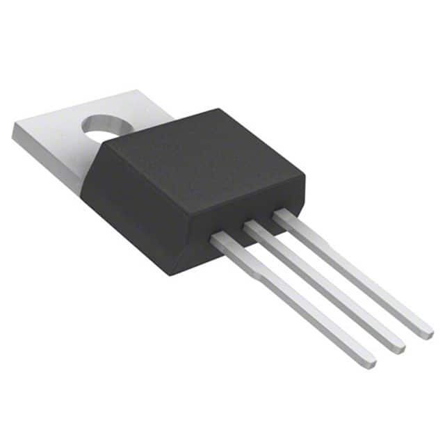
- Package: The SBR40U200CT is typically available in a TO-263AB package.
- Essence: It provides efficient rectification and voltage regulation in various electronic circuits.
- Packaging/Quantity: The SBR40U200CT is usually packaged in reels or tubes, with quantities varying based on manufacturer specifications.
Specifications
- Voltage Rating: 200V
- Forward Current: 40A
- Reverse Leakage Current: < 500µA
- Operating Temperature Range: -65°C to +175°C
- Storage Temperature Range: -65°C to +175°C
Detailed Pin Configuration
The SBR40U200CT typically has three pins: 1. Anode 2. Cathode 3. Gate (for some variants)
Functional Features
- Low forward voltage drop
- High switching speed
- Low reverse leakage current
- High thermal stability
Advantages and Disadvantages
Advantages
- Efficient power conversion
- Fast switching characteristics
- Low power dissipation
- Compact form factor
Disadvantages
- Higher cost compared to standard rectifiers
- Sensitivity to overvoltage conditions
Working Principles
The SBR40U200CT operates based on the Schottky barrier principle, where the metal-semiconductor junction allows for fast switching and low forward voltage drop. When a forward bias is applied, the diode conducts with minimal voltage loss, making it suitable for high-frequency applications.
Detailed Application Field Plans
The SBR40U200CT finds extensive use in the following applications: - Switching power supplies - Voltage clamping circuits - Reverse polarity protection - DC-DC converters - Solar inverters
Detailed and Complete Alternative Models
Some alternative models to the SBR40U200CT include: - SBR30U200CT - SBR50U200CT - SBR60U200CT - SBR80U200CT
These alternatives offer similar performance characteristics and can be used as substitutes based on specific design requirements.
In conclusion, the SBR40U200CT is a versatile Schottky Barrier Rectifier with excellent characteristics suitable for various power electronics applications.
[Word Count: 410]
Senaraikan 10 soalan dan jawapan biasa yang berkaitan dengan aplikasi SBR40U200CT dalam penyelesaian teknikal
What is the maximum voltage rating of SBR40U200CT?
- The maximum voltage rating of SBR40U200CT is 200 volts.
What is the typical forward voltage drop of SBR40U200CT?
- The typical forward voltage drop of SBR40U200CT is around 0.65 volts at a forward current of 20A.
What is the reverse recovery time of SBR40U200CT?
- The reverse recovery time of SBR40U200CT is typically 35 nanoseconds.
What is the maximum forward current rating of SBR40U200CT?
- The maximum forward current rating of SBR40U200CT is 40A.
What are the typical applications for SBR40U200CT?
- SBR40U200CT is commonly used in power supplies, inverters, and motor control applications.
What is the operating temperature range of SBR40U200CT?
- The operating temperature range of SBR40U200CT is -55°C to 175°C.
Does SBR40U200CT require a heatsink for operation?
- It is recommended to use a heatsink when operating SBR40U200CT at high currents or in high-temperature environments.
Is SBR40U200CT RoHS compliant?
- Yes, SBR40U200CT is RoHS compliant, making it suitable for environmentally friendly designs.
Can SBR40U200CT be used in parallel to increase current handling capability?
- Yes, SBR40U200CT can be used in parallel to increase current handling capability in certain applications.
What are the key advantages of using SBR40U200CT over traditional diodes?
- SBR40U200CT offers lower forward voltage drop, faster switching speed, and reduced reverse recovery time compared to traditional diodes, making it more efficient in many applications.