

74HC257DB,112
Product Overview
- Category: Integrated Circuit (IC)
- Use: Data Selector/Multiplexer
- Characteristics: High-speed operation, low power consumption
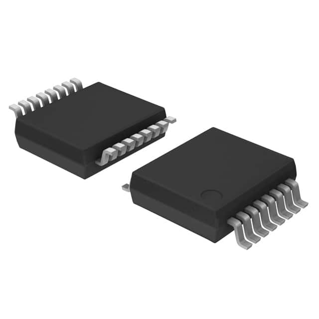
- Package: SOIC (Small Outline Integrated Circuit)
- Essence: A quad 2-input multiplexer with 3-state outputs
- Packaging/Quantity: Tape and Reel, 2500 units per reel
Specifications
- Supply Voltage Range: 2V to 6V
- Input Voltage Range: 0V to VCC
- Output Voltage Range: 0V to VCC
- Operating Temperature Range: -40°C to +125°C
- Propagation Delay Time: 15ns (typical)
- Output Current: ±25mA
- Input Capacitance: 3.5pF
- Power Dissipation: 500mW
Pin Configuration
The 74HC257DB,112 has a total of 16 pins. The pin configuration is as follows:
- GND (Ground)
- I0a (Input A for Multiplexer 0)
- I1a (Input B for Multiplexer 0)
- I0b (Input A for Multiplexer 1)
- I1b (Input B for Multiplexer 1)
- I0c (Input A for Multiplexer 2)
- I1c (Input B for Multiplexer 2)
- I0d (Input A for Multiplexer 3)
- I1d (Input B for Multiplexer 3)
- E (Enable Input)
- Y0 (Output for Multiplexer 0)
- Y1 (Output for Multiplexer 1)
- Y2 (Output for Multiplexer 2)
- Y3 (Output for Multiplexer 3)
- VCC (Positive Power Supply)
- GND (Ground)
Functional Features
- Quad 2-input multiplexer with 3-state outputs
- Common enable input for all multiplexers
- High-speed operation allows for efficient data selection
- Low power consumption ensures energy efficiency
- 3-state outputs provide flexibility in connecting multiple devices
Advantages and Disadvantages
Advantages: - High-speed operation enables quick data selection - Low power consumption reduces energy usage - 3-state outputs offer flexibility in connecting multiple devices
Disadvantages: - Limited number of inputs and outputs - Not suitable for applications requiring a large number of multiplexers
Working Principles
The 74HC257DB,112 is a quad 2-input multiplexer with 3-state outputs. It selects one of the four input signals based on the control signal provided at the enable input. The selected input is then routed to the corresponding output. The 3-state outputs allow the device to be effectively disconnected from the bus when not in use.
Detailed Application Field Plans
The 74HC257DB,112 can be used in various applications, including:
- Data routing and selection in digital systems
- Address decoding in memory systems
- Input/output expansion in microcontroller-based systems
- Signal switching in communication systems
Alternative Models
Here are some alternative models that can be considered as alternatives to the 74HC257DB,112:
- CD74HC257E: Similar quad 2-input multiplexer with 3-state outputs, available in DIP package.
- SN74HC257N: Quad 2-input multiplexer with 3-state outputs, available in DIP package.
- MC74HC257AN: Quad 2-input multiplexer with 3-state outputs, available in DIP package.
These alternative models offer similar functionality and can be used as replacements depending on the specific requirements of the application.
In conclusion, the 74HC257DB,112 is a versatile integrated circuit that provides efficient data selection and routing capabilities. Its high-speed operation, low power consumption, and 3-state outputs make it suitable for various digital systems and communication applications.
Senaraikan 10 soalan dan jawapan biasa yang berkaitan dengan aplikasi 74HC257DB,112 dalam penyelesaian teknikal
Sure! Here are 10 common questions and answers related to the application of 74HC257DB,112 in technical solutions:
Q: What is the 74HC257DB,112? A: The 74HC257DB,112 is a quad 2-input multiplexer with 3-state outputs, commonly used in digital logic circuits.
Q: What is the purpose of a multiplexer? A: A multiplexer is used to select one of several input signals and route it to a single output line.
Q: How many inputs does the 74HC257DB,112 have? A: The 74HC257DB,112 has four inputs, labeled A0, A1, A2, and A3.
Q: Can the 74HC257DB,112 handle both analog and digital signals? A: No, the 74HC257DB,112 is designed to work with digital signals only.
Q: How many output lines does the 74HC257DB,112 have? A: The 74HC257DB,112 has two output lines, labeled Y and Y̅ (Y-bar).
Q: What is the purpose of the 3-state outputs? A: The 3-state outputs allow the outputs to be disabled or put into a high-impedance state when not in use.
Q: What is the maximum voltage the 74HC257DB,112 can handle? A: The 74HC257DB,112 can handle a maximum voltage of 5.5V.
Q: Can the 74HC257DB,112 be cascaded to increase the number of inputs? A: Yes, multiple 74HC257DB,112 chips can be cascaded together to increase the number of inputs.
Q: What is the power supply voltage range for the 74HC257DB,112? A: The power supply voltage range for the 74HC257DB,112 is typically between 2V and 6V.
Q: Can the 74HC257DB,112 be used in high-speed applications? A: Yes, the 74HC257DB,112 is designed for high-speed operation and can be used in such applications.
Please note that the answers provided here are general and may vary depending on specific datasheet specifications and application requirements.