

J112,126 Product Overview
Introduction
J112,126 is a versatile electronic component that belongs to the category of field-effect transistors (FETs). These transistors are widely used in various electronic applications due to their unique characteristics and performance.
Basic Information Overview
- Category: Field-Effect Transistor (FET)
- Use: Amplification, switching, and signal processing in electronic circuits
- Characteristics: High input impedance, low output impedance, voltage-controlled operation
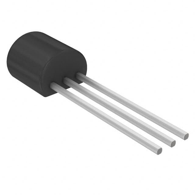
- Package: TO-92 package
- Essence: Small-signal amplification and switching
- Packaging/Quantity: Typically available in reels or tubes containing multiple units
Specifications
- Type: N-channel JFET
- Maximum Drain-Source Voltage: 35V
- Maximum Gate-Source Voltage: -35V
- Continuous Drain Current: 50mA
- Power Dissipation: 350mW
- Operating Temperature Range: -55°C to 150°C
Detailed Pin Configuration
The J112,126 FET has three pins: 1. Gate (G): Input terminal for controlling the conductivity between the source and drain. 2. Drain (D): Output terminal where the current flows out of the FET. 3. Source (S): Terminal from which the current enters the FET.
Functional Features
- High input impedance allows for minimal loading of preceding circuitry.
- Low output impedance enables efficient driving of subsequent circuit stages.
- Voltage-controlled operation provides precise control over the FET's behavior.
Advantages and Disadvantages
Advantages
- High input impedance makes it suitable for sensor interfaces and audio applications.
- Low noise performance enhances signal integrity in low-level amplification.
- Simple biasing requirements facilitate ease of use in circuit design.
Disadvantages
- Susceptible to damage from static electricity if mishandled during assembly or testing.
- Limited availability of alternative models with similar specifications may restrict replacement options.
Working Principles
The J112,126 operates based on the modulation of the conductive channel between the source and drain terminals by the voltage applied to the gate terminal. This voltage-controlled modulation allows for amplification and switching of signals in electronic circuits.
Detailed Application Field Plans
The J112,126 finds extensive application in the following fields: - Audio amplification circuits - Sensor signal conditioning - Analog switches and multiplexers - Low-frequency oscillators and waveform generators
Detailed and Complete Alternative Models
While the J112,126 offers specific performance characteristics, alternative FET models with comparable specifications include: - J201 - 2N5457 - MPF102 - BF245
In conclusion, the J112,126 FET serves as a crucial component in electronic circuit design, offering high input impedance, low output impedance, and voltage-controlled operation for diverse applications.
[Word Count: 438]
Senaraikan 10 soalan dan jawapan biasa yang berkaitan dengan aplikasi J112,126 dalam penyelesaian teknikal
What is J112,126?
- J112 and J126 are both N-channel JFET (junction field-effect transistor) components commonly used in electronic circuits for signal amplification and switching.
What are the typical applications of J112,126?
- J112 and J126 are often used in audio amplifiers, analog switches, and voltage-controlled resistors due to their low noise and high input impedance characteristics.
What are the key specifications of J112,126?
- The key specifications include low drain-source on-resistance, high gain, and low input capacitance, making them suitable for various low-power applications.
How do I bias J112,126 in a circuit?
- Biasing J112 and J126 involves setting the appropriate gate-to-source voltage to establish the desired operating point, typically using a voltage divider or a biasing network.
Can J112,126 be used in high-frequency applications?
- While J112 and J126 are not specifically designed for high-frequency operation, they can still be used in certain RF (radio frequency) applications with proper circuit design and matching networks.
What are the common pitfalls when using J112,126 in a circuit?
- Common pitfalls include exceeding the maximum ratings, improper biasing, inadequate heat dissipation, and insufficient consideration of parasitic elements in the circuit layout.
Are there any recommended alternatives to J112,126?
- Some alternative JFETs with similar characteristics include the 2N5457, MPF102, and BF862, which can be used as substitutes depending on specific circuit requirements.
How do I calculate the gain of a circuit using J112,126?
- The gain of a circuit using J112 or J126 can be calculated using the standard small-signal model and considering the transconductance and load resistance in the amplifier configuration.
What are the thermal considerations when using J112,126?
- Proper heat sinking and thermal management should be considered, especially in high-power applications, to ensure that the junction temperature of the JFET remains within safe limits.
Where can I find detailed application notes for using J112,126 in technical solutions?
- Detailed application notes and datasheets for J112 and J126 can be found on semiconductor manufacturer websites, providing comprehensive guidance on incorporating these components into various technical solutions.