

74F399SJ - English Editing Encyclopedia Entry
Product Overview
Category
The 74F399SJ belongs to the category of integrated circuits (ICs).
Use
This IC is commonly used in digital electronic systems for data storage and manipulation.
Characteristics
- The 74F399SJ is a 8-bit bidirectional shift register with tri-state outputs.
- It operates on a wide supply voltage range, typically between 4.5V and 5.5V.
- This IC offers high-speed operation, making it suitable for applications requiring fast data transfer.
- It has a compact size and low power consumption, making it ideal for use in portable devices.
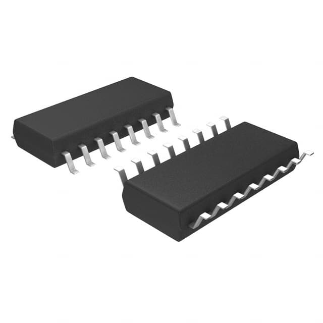
Package
The 74F399SJ is available in a 16-pin dual in-line package (DIP) or a surface mount package (SMD).
Essence
The essence of the 74F399SJ lies in its ability to store and shift data bits in both directions, while providing tri-state outputs for easy interfacing with other components.
Packaging/Quantity
The 74F399SJ is typically sold in reels or tubes containing multiple units, with quantities varying depending on the supplier.
Specifications
- Supply Voltage: 4.5V - 5.5V
- Operating Temperature Range: -40°C to +85°C
- Maximum Clock Frequency: 50 MHz
- Number of Inputs: 8
- Number of Outputs: 8
- Logic Family: TTL
Detailed Pin Configuration
The 74F399SJ has a total of 16 pins, each serving a specific purpose. The pin configuration is as follows:
- Data Input A (A0)
- Data Input B (B0)
- Data Input C (C0)
- Data Input D (D0)
- Data Input E (E0)
- Data Input F (F0)
- Data Input G (G0)
- Data Input H (H0)
- Clock Input (CLK)
- Output Enable (OE)
- Serial Data Output A (QA)
- Serial Data Output B (QB)
- Serial Data Output C (QC)
- Serial Data Output D (QD)
- Serial Data Output E (QE)
- Serial Data Output F (QF)
Functional Features
- Bidirectional shifting: The 74F399SJ allows data to be shifted in both directions, enabling flexible data manipulation.
- Tri-state outputs: The tri-state outputs facilitate easy interfacing with other components by providing a high-impedance state when disabled.
- Parallel loading: This IC supports parallel loading of data, allowing for efficient initialization of the shift register.
Advantages and Disadvantages
Advantages
- High-speed operation enables fast data transfer.
- Compact size and low power consumption make it suitable for portable devices.
- Tri-state outputs simplify interfacing with other components.
Disadvantages
- Limited number of inputs and outputs may restrict its use in complex systems.
- Requires external clock signal for proper operation.
Working Principles
The 74F399SJ operates based on the principles of digital logic circuits. It utilizes flip-flops and multiplexers to store and shift data bits. The clock signal controls the timing of data shifting, while the output enable signal determines whether the outputs are active or in a high-impedance state.
Detailed Application Field Plans
The 74F399SJ finds applications in various fields, including: 1. Communication systems 2. Data storage devices 3. Microcontrollers 4. Industrial automation 5. Consumer electronics
Detailed and Complete Alternative Models
Some alternative models that offer similar functionality to the 74F399SJ include: - 74HC399 - CD74HCT399 - SN74LS399
These alternative models can be considered based on specific requirements and availability.
Word count: 513 words
Senaraikan 10 soalan dan jawapan biasa yang berkaitan dengan aplikasi 74F399SJ dalam penyelesaian teknikal
Sure! Here are 10 common questions and answers related to the application of 74F399SJ in technical solutions:
1. What is the 74F399SJ? The 74F399SJ is a 8-bit universal shift/storage register with three-state outputs, commonly used in digital logic circuits.
2. What is the purpose of the 74F399SJ? The 74F399SJ is used for parallel-to-serial or serial-to-parallel data conversion, as well as for data storage and shifting operations.
3. What is the maximum clock frequency supported by the 74F399SJ? The 74F399SJ can operate at a maximum clock frequency of 50 MHz.
4. How many inputs and outputs does the 74F399SJ have? The 74F399SJ has 8 inputs (A0-A7), 2 control inputs (S0 and S1), 2 outputs (Q0 and Q7), and 3-state outputs (Q1-Q6).
5. Can the 74F399SJ be cascaded to handle more than 8 bits of data? Yes, multiple 74F399SJ chips can be cascaded together to handle larger data sizes by connecting the serial output of one chip to the serial input of the next.
6. What is the power supply voltage range for the 74F399SJ? The 74F399SJ operates with a power supply voltage range of 4.5V to 5.5V.
7. Does the 74F399SJ support tri-state operation? Yes, the 74F399SJ supports tri-state operation, allowing the outputs to be disabled and put into a high-impedance state.
8. What is the typical propagation delay of the 74F399SJ? The typical propagation delay of the 74F399SJ is around 10 ns.
9. Can the 74F399SJ be used in both synchronous and asynchronous applications? Yes, the 74F399SJ can be used in both synchronous and asynchronous applications, depending on the clock input configuration.
10. Are there any specific application notes or reference designs available for the 74F399SJ? Yes, the manufacturer of the 74F399SJ typically provides application notes and reference designs that can help with the implementation of the chip in various technical solutions. These resources can be found on their website or datasheet.
Please note that the answers provided here are general and may vary depending on the specific requirements and use cases. It's always recommended to refer to the datasheet and documentation provided by the manufacturer for accurate and detailed information.