

FGH40N65UFDTU
Introduction
The FGH40N65UFDTU is a power semiconductor device belonging to the category of Insulated Gate Bipolar Transistors (IGBTs). This entry provides an overview of the basic information, specifications, pin configuration, functional features, advantages and disadvantages, working principles, application field plans, and alternative models of the FGH40N65UFDTU.
Basic Information Overview
- Category: Power Semiconductor Device
- Use: Power switching applications in various electronic systems
- Characteristics: High voltage and current handling capability, low on-state voltage drop, fast switching speed
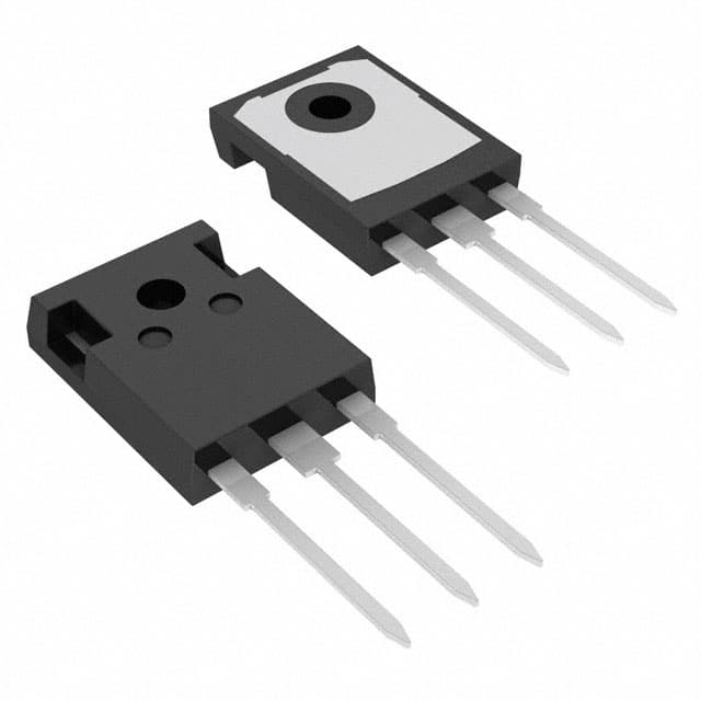
- Package: TO-247
- Essence: Efficient power control and management
- Packaging/Quantity: Typically packaged individually, quantity varies based on manufacturer's specifications
Specifications
- Voltage Rating: 650V
- Current Rating: 40A
- Maximum Operating Temperature: 150°C
- Gate-Emitter Voltage: ±20V
- Collector-Emitter Saturation Voltage: 1.8V
- Turn-On Delay Time: 55ns
- Turn-Off Delay Time: 130ns
Detailed Pin Configuration
The FGH40N65UFDTU IGBT typically has the following pin configuration: 1. Collector (C) 2. Gate (G) 3. Emitter (E)
Functional Features
- High voltage and current handling capacity
- Low on-state voltage drop leading to reduced power losses
- Fast switching speed enabling efficient power control
- Robust construction for reliable performance in demanding applications
Advantages and Disadvantages
Advantages
- Enhanced power efficiency
- Suitable for high-power applications
- Reliable and robust design
- Fast switching speed
Disadvantages
- Higher cost compared to standard power transistors
- Requires careful thermal management due to high power dissipation
Working Principles
The FGH40N65UFDTU operates based on the principles of controlling the flow of current between the collector and emitter terminals using the gate signal. When a suitable voltage is applied to the gate terminal, it allows the current to flow between the collector and emitter, effectively controlling the power flow through the device.
Detailed Application Field Plans
The FGH40N65UFDTU finds extensive use in various applications including: - Motor drives - Uninterruptible Power Supplies (UPS) - Renewable energy systems - Industrial power electronics - Electric vehicle powertrains
Detailed and Complete Alternative Models
Some alternative models to the FGH40N65UFDTU include: - IRGP4063DPBF - IXGH40N60C2D1 - STGW40NC60WD
In conclusion, the FGH40N65UFDTU is a high-performance IGBT designed for power switching applications, offering efficient power control, high reliability, and suitability for diverse high-power electronic systems.
[Word Count: 366]
Senaraikan 10 soalan dan jawapan biasa yang berkaitan dengan aplikasi FGH40N65UFDTU dalam penyelesaian teknikal
What is FGH40N65UFDTU?
- FGH40N65UFDTU is a high-voltage, fast-switching IGBT (Insulated Gate Bipolar Transistor) designed for use in various technical solutions requiring efficient power control.
What are the key features of FGH40N65UFDTU?
- FGH40N65UFDTU features include high voltage capability, low saturation voltage, fast switching speed, and ruggedness for reliable performance in demanding applications.
In what technical solutions can FGH40N65UFDTU be used?
- FGH40N65UFDTU is commonly used in applications such as motor drives, renewable energy systems, induction heating, welding equipment, and power supplies.
What are the benefits of using FGH40N65UFDTU in technical solutions?
- The benefits of using FGH40N65UFDTU include improved energy efficiency, reduced power losses, enhanced system reliability, and compact design due to its high performance characteristics.
What are the typical operating conditions for FGH40N65UFDTU?
- FGH40N65UFDTU operates under typical conditions of high voltage (up to 650V), high current, and high frequency, making it suitable for demanding power electronics applications.
How does FGH40N65UFDTU compare to other IGBTs in the market?
- FGH40N65UFDTU stands out due to its combination of high voltage capability, low saturation voltage, and fast switching speed, making it a preferred choice for many high-power applications.
What cooling methods are recommended for FGH40N65UFDTU?
- Adequate cooling methods such as heat sinks, fans, or liquid cooling systems should be employed to maintain the temperature within the specified limits for optimal performance and reliability.
Are there any application notes or reference designs available for using FGH40N65UFDTU?
- Yes, manufacturers often provide application notes, reference designs, and evaluation boards to assist engineers in implementing FGH40N65UFDTU in their technical solutions.
What protection features does FGH40N65UFDTU offer?
- FGH40N65UFDTU typically includes built-in protection features such as short-circuit protection, overcurrent protection, and temperature monitoring to safeguard the device and the overall system.
Where can I purchase FGH40N65UFDTU and get technical support?
- FGH40N65UFDTU can be purchased from authorized distributors and manufacturers, who also provide technical support, datasheets, and application support to assist with integration into technical solutions.