

J105 Transistor: Product Overview and Specifications
Introduction
The J105 transistor is a key component in the field of electronics, belonging to the category of field-effect transistors (FETs). This versatile device offers a wide range of applications and characteristics that make it an essential tool for various electronic circuits.
Basic Information Overview
- Category: Field-Effect Transistor (FET)
- Use: Amplification, switching, and signal processing in electronic circuits
- Characteristics: High input impedance, low noise, and low power consumption
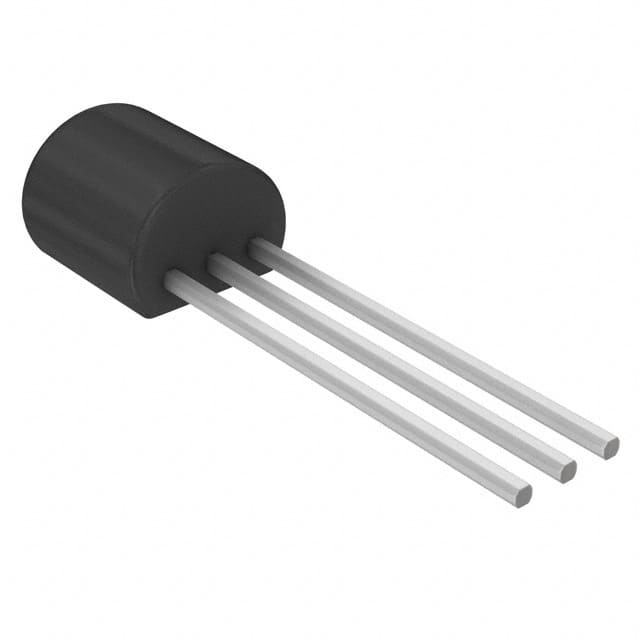
- Package: TO-92 package
- Essence: Small-signal N-channel junction field-effect transistor
- Packaging/Quantity: Typically available in packs of 10 or 100 units
Specifications
The J105 transistor features the following specifications: - Maximum Drain-Source Voltage (Vds): 35V - Maximum Gate-Source Voltage (Vgs): ±25V - Continuous Drain Current (Id): 50mA - Power Dissipation (Pd): 350mW - Operating Temperature Range: -55°C to 150°C
Detailed Pin Configuration
The J105 transistor has a standard pin configuration with three terminals: 1. Gate (G): Input terminal for controlling the flow of current 2. Drain (D): Output terminal for the amplified or switched current 3. Source (S): Terminal connected to the common ground
Functional Features
- Amplification: The J105 transistor can amplify small signals with high input impedance, making it suitable for use in audio amplifiers and preamplifier circuits.
- Switching: It can efficiently switch electronic signals in digital circuits due to its low on-resistance and fast switching speed.
- Low Noise: The transistor's low noise characteristics make it ideal for use in sensitive signal processing applications.
Advantages and Disadvantages
Advantages
- High input impedance allows for easy interfacing with other electronic components
- Low power consumption makes it suitable for battery-operated devices
- Versatile applications in both analog and digital circuits
Disadvantages
- Limited maximum drain-source voltage and current handling capabilities compared to some other FETs
- Sensitivity to electrostatic discharge (ESD) requires careful handling during assembly and usage
Working Principles
The J105 transistor operates based on the principles of field-effect modulation, where the voltage applied to the gate terminal controls the conductivity between the source and drain terminals. By modulating the electric field within the semiconductor channel, the transistor can amplify or switch electronic signals effectively.
Detailed Application Field Plans
The J105 transistor finds extensive use in various electronic applications, including: - Audio amplifiers and preamplifiers - Signal processing circuits in communication systems - Analog and digital switches in control systems - Low-power sensor interfaces in IoT devices
Detailed and Complete Alternative Models
For users seeking alternative models with similar characteristics, the following transistors can be considered: - J112 - 2N5457 - MPF102
In conclusion, the J105 transistor offers a balance of performance and versatility, making it a valuable component in electronic circuit design across a wide range of applications.
Word Count: 498
Senaraikan 10 soalan dan jawapan biasa yang berkaitan dengan aplikasi J105 dalam penyelesaian teknikal
What is J105?
- J105 is a common NPN bipolar junction transistor used in electronic circuits.
What are the typical applications of J105?
- J105 is commonly used in audio amplifier circuits, switching applications, and signal amplification.
What are the key characteristics of J105?
- J105 has low noise, high gain, and low distortion, making it suitable for audio applications.
What are the voltage and current ratings for J105?
- The maximum voltage rating for J105 is typically around 40V, and the maximum continuous collector current is around 100mA.
How do I identify the pinout of J105?
- The pinout of J105 is typically identified as the emitter (E), base (B), and collector (C) pins.
Can J105 be used in high-frequency applications?
- J105 is not typically recommended for high-frequency applications due to its relatively slow transition frequency.
What are some common alternatives to J105?
- Alternatives to J105 include transistors such as 2N3904, BC547, and BC548, which have similar characteristics and can be used in similar applications.
How should J105 be biased in a circuit?
- J105 is typically biased using a suitable resistor network to ensure proper operating conditions and stability in the circuit.
What are the thermal considerations for J105 in a circuit?
- Proper heat sinking may be required for J105 in high-power or continuous operation to prevent overheating and ensure long-term reliability.
Where can I find detailed datasheets and application notes for J105?
- Datasheets and application notes for J105 can be found on semiconductor manufacturer websites or electronics component distributors' platforms.