

J113 Transistor: Encyclopedia Entry
Introduction
The J113 transistor is a crucial component in electronic circuits, belonging to the category of field-effect transistors (FETs). This entry provides an overview of the J113 transistor, including its basic information, specifications, pin configuration, functional features, advantages and disadvantages, working principles, application field plans, and alternative models.
Basic Information Overview
- Category: Field-Effect Transistor (FET)
- Use: The J113 transistor is commonly used as a switch or amplifier in electronic circuits.
- Characteristics: It exhibits high input impedance, low output impedance, and low power consumption.
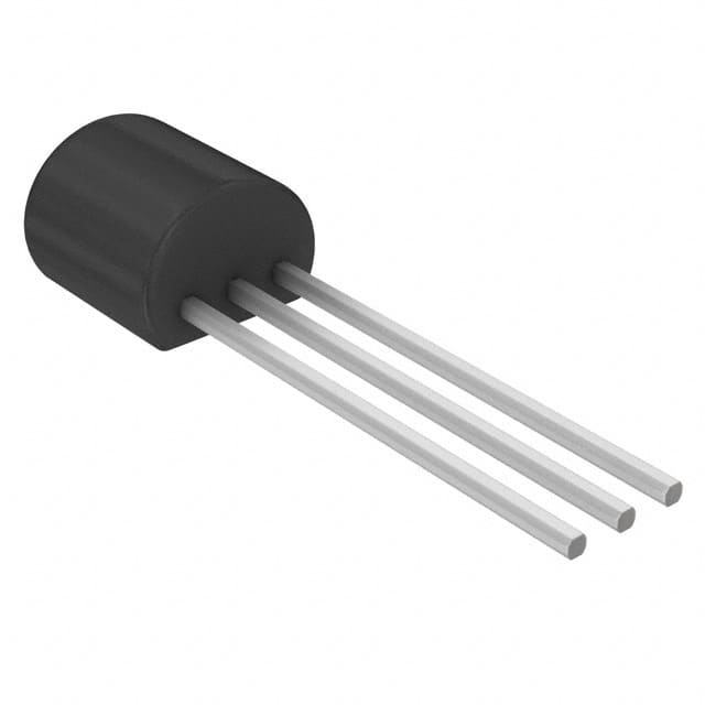
- Package: Typically available in TO-92 packaging.
- Essence: The J113 transistor is known for its high input impedance and low noise characteristics.
- Packaging/Quantity: Available in various packaging options, typically sold in quantities of 10 or more.
Specifications
- Maximum Drain-Source Voltage: 35V
- Maximum Gate-Source Voltage: ±25V
- Continuous Drain Current: 50mA
- Power Dissipation: 350mW
- Operating Temperature Range: -55°C to 150°C
Detailed Pin Configuration
The J113 transistor has three pins: 1. Gate (G): Controls the conductivity between the source and drain terminals. 2. Drain (D): Connects to the positive supply voltage in most applications. 3. Source (S): Connects to the ground or common reference point.
Functional Features
- High input impedance allows for minimal loading of preceding stages.
- Low output impedance enables it to drive loads directly.
- Suitable for use in low-power applications due to its low power consumption.
Advantages and Disadvantages
Advantages
- High input impedance makes it suitable for use in high-impedance circuits.
- Low noise characteristics make it ideal for low-level signal amplification.
Disadvantages
- Limited maximum drain-source voltage and current compared to other FETs.
- Sensitivity to static electricity can pose handling challenges.
Working Principles
The J113 transistor operates based on the field effect, where the conductivity between the source and drain terminals is controlled by the voltage applied to the gate terminal. When a voltage is applied to the gate, it modulates the conductivity between the source and drain, allowing it to function as a switch or amplifier.
Detailed Application Field Plans
The J113 transistor finds applications in various electronic circuits, including: - Audio amplifiers - Oscillators - Signal processing circuits - Low-frequency switching circuits
Detailed and Complete Alternative Models
Some alternative models to the J113 transistor include: - J112 - J201 - 2N5457 - 2N5484
In conclusion, the J113 transistor is a versatile component with high input impedance, making it suitable for various electronic applications. Its unique characteristics and specifications position it as a valuable asset in circuit design and implementation.
[Word Count: 413]
Senaraikan 10 soalan dan jawapan biasa yang berkaitan dengan aplikasi J113 dalam penyelesaian teknikal
What is J113?
- J113 is a general-purpose N-channel JFET (junction field-effect transistor) commonly used in electronic circuits.
What are the typical applications of J113?
- J113 is often used for signal amplification, switching, and voltage-controlled resistors in various electronic circuits.
What are the key characteristics of J113?
- J113 features low noise, high input impedance, and can operate at low power levels, making it suitable for many audio and sensor applications.
How do I identify the pinout of J113?
- The pinout of J113 is typically identified as gate (G), drain (D), and source (S). The datasheet provides specific details for pin identification.
What are the recommended operating conditions for J113?
- J113 operates well within a wide range of voltages and temperatures, but it's important to refer to the datasheet for precise operating conditions.
Can J113 be used for audio amplifier applications?
- Yes, J113 is commonly used in audio amplifier circuits due to its low noise and high input impedance characteristics.
How do I bias J113 for proper operation?
- Biasing J113 involves setting the appropriate voltage levels at the gate terminal to ensure proper conduction and amplification.
Are there any common pitfalls when using J113 in circuits?
- It's important to avoid exceeding the maximum ratings specified in the datasheet, such as voltage and current limits, to prevent damage to the J113.
Can J113 be used in switching applications?
- Yes, J113 can be used as a switch in electronic circuits, especially in low-power applications where its characteristics are beneficial.
Where can I find more detailed information about using J113 in technical solutions?
- Detailed information about using J113 can be found in the datasheet provided by the manufacturer, which includes application notes and circuit examples.