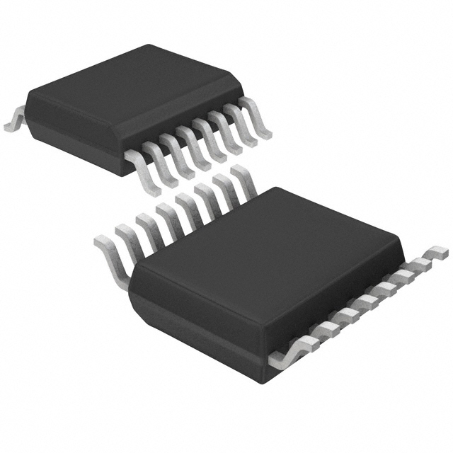
NLSF595DTR2 - English Editing Encyclopedia Entry
Product Overview
Category
NLSF595DTR2 belongs to the category of integrated circuits (ICs).
Use
This product is commonly used in electronic devices for controlling and driving light-emitting diodes (LEDs).
Characteristics
- NLSF595DTR2 is a shift register with an output latch, designed specifically for LED control applications.
- It operates at a wide voltage range, making it suitable for various electronic systems.
- The IC has a high-speed data transfer capability, enabling efficient LED control.
Package
NLSF595DTR2 is available in a small outline package (SOP) format.
Essence
The essence of NLSF595DTR2 lies in its ability to provide precise control over LED lighting, enhancing the visual experience in electronic devices.
Packaging/Quantity
This product is typically packaged in reels, containing a specific quantity of ICs per reel. The exact quantity may vary depending on the manufacturer's specifications.
Specifications
- Supply Voltage: 3V to 5.5V
- Maximum Clock Frequency: 30 MHz
- Number of Output Channels: 8
- Output Current: 20 mA per channel
- Operating Temperature Range: -40°C to +85°C
Detailed Pin Configuration
- VCC - Power supply voltage input
- GND - Ground reference
- SER - Serial data input
- SRCLK - Shift register clock input
- RCLK - Register clock input
- OE - Output enable input
- Q0-Q7 - Output channels for LED control
- SRCLR - Shift register clear input
Functional Features
- NLSF595DTR2 incorporates a serial-in, parallel-out shift register along with an output latch, allowing for easy control of LED states.
- It supports cascading multiple ICs to control a larger number of LEDs.
- The output enable (OE) pin provides the ability to disable all outputs simultaneously, conserving power when necessary.
Advantages and Disadvantages
Advantages
- Precise control over LED lighting patterns and intensity.
- Wide operating voltage range enables compatibility with various electronic systems.
- High-speed data transfer capability for efficient LED control.
- Ability to cascade multiple ICs for controlling a large number of LEDs.
Disadvantages
- Limited number of output channels (8 channels).
- Requires additional components for driving high-power LEDs.
Working Principles
NLSF595DTR2 operates based on the principle of serial-in, parallel-out shift registers. It receives serial data input (SER) and shifts it through the internal register upon receiving clock signals (SRCLK). The register clock (RCLK) latches the shifted data into the output channels (Q0-Q7), controlling the state of connected LEDs. The output enable (OE) pin allows for enabling or disabling all outputs simultaneously.
Detailed Application Field Plans
NLSF595DTR2 finds extensive application in various electronic devices that incorporate LED lighting. Some notable applications include:
- LED displays: Used in digital signage, scoreboards, and information boards.
- Automotive lighting: Controls LED headlights, taillights, and interior lighting.
- Decorative lighting: Enables dynamic lighting effects in architectural and entertainment settings.
- Consumer electronics: Controls LED indicators and backlighting in televisions, monitors, and appliances.
Detailed and Complete Alternative Models
- NLSF595D - Similar to NLSF595DTR2 but available in a different package format.
- MAX7219 - Integrated circuit for LED control with additional features like multiplexing and segment drivers.
- TLC5940 - Provides control over a larger number of LEDs with additional grayscale control capabilities.
Note: This is not an exhaustive list, and there are several alternative models available in the market catering to different requirements.
Word count: 529 words
Senaraikan 10 soalan dan jawapan biasa yang berkaitan dengan aplikasi NLSF595DTR2 dalam penyelesaian teknikal
Sure! Here are 10 common questions and answers related to the application of NLSF595DTR2 in technical solutions:
Q: What is NLSF595DTR2? A: NLSF595DTR2 is a specific model of an integrated circuit (IC) used for driving LEDs in various technical applications.
Q: What is the purpose of NLSF595DTR2? A: The purpose of NLSF595DTR2 is to control and drive multiple LEDs, enabling them to display different colors and patterns.
Q: How many LEDs can NLSF595DTR2 drive? A: NLSF595DTR2 can drive up to 8 individual LEDs or LED segments.
Q: What voltage range does NLSF595DTR2 operate on? A: NLSF595DTR2 operates on a voltage range of typically 3.3V to 5V.
Q: Can NLSF595DTR2 be used with both common anode and common cathode LEDs? A: Yes, NLSF595DTR2 can be used with both common anode and common cathode LEDs, depending on the circuit configuration.
Q: Does NLSF595DTR2 support dimming or brightness control of LEDs? A: Yes, NLSF595DTR2 supports PWM (Pulse Width Modulation) dimming, allowing precise control over the brightness of LEDs.
Q: Is NLSF595DTR2 compatible with microcontrollers or Arduino boards? A: Yes, NLSF595DTR2 is commonly used with microcontrollers and Arduino boards, as it can be easily interfaced with these platforms.
Q: Can NLSF595DTR2 be cascaded to drive more than 8 LEDs? A: Yes, multiple NLSF595DTR2 ICs can be cascaded together to drive a larger number of LEDs in a daisy-chain configuration.
Q: What is the maximum data transfer rate supported by NLSF595DTR2? A: NLSF595DTR2 supports a maximum data transfer rate of typically 30 MHz.
Q: Are there any specific precautions to consider when using NLSF595DTR2? A: It is important to ensure that the power supply voltage and current are within the specified limits, and proper heat dissipation measures should be taken as per the datasheet guidelines.
Please note that the answers provided here are general and may vary depending on the specific application and implementation of NLSF595DTR2.


