

TIP117G Transistor
Introduction
The TIP117G transistor is a versatile electronic component that belongs to the category of power transistors. It is commonly used in various electronic applications due to its unique characteristics and functional features.
Basic Information Overview
- Category: Power Transistor
- Use: Amplification, Switching
- Characteristics: High voltage capability, high current capability, low saturation voltage
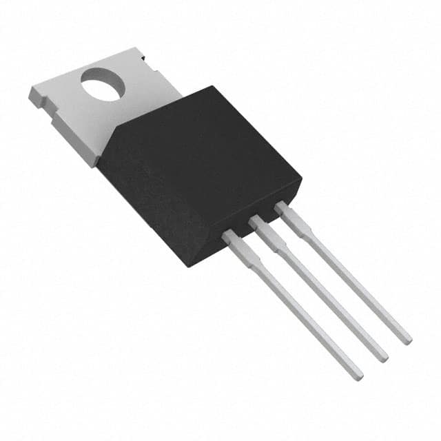
- Package: TO-220
- Essence: NPN Darlington Transistor
- Packaging/Quantity: Typically available in reels or tubes containing multiple units
Specifications
- Collector-Emitter Voltage (VCEO): 100V
- Collector Current (IC): 5A
- Power Dissipation (Pd): 65W
- DC Current Gain (hFE): 1000 (min) at IC = 3A
Detailed Pin Configuration
The TIP117G transistor has a standard TO-220 package with three pins: 1. Base (B): Input terminal for controlling the flow of current through the transistor. 2. Collector (C): Terminal connected to the positive supply voltage. 3. Emitter (E): Terminal connected to the ground or common reference point.
Functional Features
- Darlington Pair Configuration: Provides high current gain and improved performance.
- Low Saturation Voltage: Ensures minimal power loss during operation.
- High Voltage Capability: Suitable for applications requiring high voltage handling.
Advantages
- High current gain allows for efficient amplification and switching.
- Low saturation voltage minimizes power dissipation and heat generation.
- Versatile application in power control circuits and amplifiers.
Disadvantages
- Higher base-emitter voltage drop compared to standard transistors.
- Limited frequency response in high-speed switching applications.
Working Principles
The TIP117G operates based on the principles of bipolar junction transistors, utilizing the Darlington pair configuration to achieve high current gain. When a small current flows into the base terminal, it controls a much larger current flowing between the collector and emitter terminals, enabling amplification or switching functions.
Detailed Application Field Plans
The TIP117G transistor finds extensive use in various electronic applications, including: - Power control circuits in motor drivers and voltage regulators. - Audio amplifiers and power supply units. - Industrial automation systems and control circuits.
Detailed and Complete Alternative Models
Some alternative models to the TIP117G transistor include: - TIP116G: Lower collector-emitter voltage rating (VCEO) of 60V. - TIP120G: Higher collector current (IC) rating of 8A. - TIP121G: Higher power dissipation (Pd) rating of 80W.
In conclusion, the TIP117G transistor offers reliable performance in power control and amplification applications, making it a valuable component in the field of electronics.
Word Count: 398
Senaraikan 10 soalan dan jawapan biasa yang berkaitan dengan aplikasi TIP117G dalam penyelesaian teknikal
What is TIP117G?
- TIP117G is a PNP (positive-negative-positive) bipolar junction transistor (BJT) commonly used for high-power switching applications.
What are the typical applications of TIP117G?
- TIP117G is commonly used in power supply circuits, motor control circuits, and high-power switching applications.
What is the maximum collector current rating of TIP117G?
- The maximum collector current rating of TIP117G is typically around 2A to 5A.
What is the maximum collector-emitter voltage rating of TIP117G?
- The maximum collector-emitter voltage rating of TIP117G is typically around 60V to 100V.
How do I properly bias TIP117G in a circuit?
- TIP117G is a PNP transistor, so it requires a negative base voltage with respect to the emitter to turn on. Proper biasing involves applying the correct base-emitter voltage to ensure proper operation.
What are the key considerations for heat dissipation when using TIP117G?
- Heat dissipation is important when using TIP117G in high-power applications. Proper heat sinking and thermal management should be considered to prevent overheating.
Can TIP117G be used for PWM (Pulse Width Modulation) applications?
- Yes, TIP117G can be used for PWM applications due to its ability to switch high currents.
What are the typical protection measures for TIP117G in a circuit?
- Typical protection measures include adding flyback diodes to protect against voltage spikes in inductive loads and ensuring proper current limiting to protect the transistor from overcurrent conditions.
What are the common failure modes of TIP117G?
- Common failure modes include thermal runaway due to inadequate heat dissipation, overcurrent leading to breakdown, and voltage spikes causing damage to the transistor.
Are there any specific layout considerations when using TIP117G in a PCB design?
- It's important to minimize trace lengths and provide adequate copper area for heat dissipation in the PCB layout. Additionally, proper isolation and clearance distances should be maintained to prevent electrical interference.