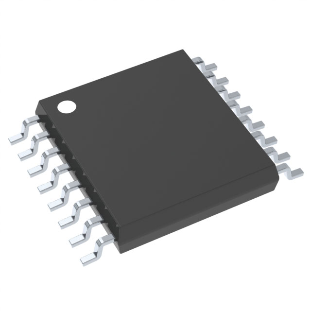
CD40257BPWG4
Product Overview
Category
CD40257BPWG4 belongs to the category of integrated circuits (ICs).
Use
This product is commonly used in digital logic applications, specifically for data multiplexing and demultiplexing.
Characteristics
- CD40257BPWG4 is a quad 2-input multiplexer/demultiplexer IC.
- It operates on a wide supply voltage range of 3V to 18V.
- The device has a high noise immunity and exhibits low power consumption.
- It is designed to be compatible with various TTL families.
Package
CD40257BPWG4 is available in a standard DIP (Dual In-line Package) format.
Essence
The essence of CD40257BPWG4 lies in its ability to efficiently multiplex and demultiplex data signals in digital systems.
Packaging/Quantity
This product is typically packaged in tubes or reels, containing a specific quantity of ICs per package. The exact packaging and quantity may vary depending on the supplier.
Specifications
- Supply Voltage Range: 3V to 18V
- Input Voltage Range: 0V to VDD
- Operating Temperature Range: -55°C to +125°C
- Output Current: ±10mA
- Propagation Delay Time: 60ns (max)
- Power Dissipation: 500mW (max)
Detailed Pin Configuration
CD40257BPWG4 consists of 16 pins, each serving a specific function:
- A0: Multiplexer Input A0
- B0: Multiplexer Input B0
- C0: Multiplexer Input C0
- D0: Multiplexer Input D0
- S: Select Input
- Y: Multiplexer Output
- GND: Ground
- Y: Demultiplexer Output Y0
- Y: Demultiplexer Output Y1
- Y: Demultiplexer Output Y2
- Y: Demultiplexer Output Y3
- S: Select Input
- C1: Multiplexer Input C1
- B1: Multiplexer Input B1
- A1: Multiplexer Input A1
- VDD: Supply Voltage
Functional Features
- CD40257BPWG4 can be used as a 2-to-1 multiplexer or a 1-to-2 demultiplexer.
- It provides a simple and efficient way to select between multiple input signals and route them to a single output or vice versa.
- The device offers a wide operating voltage range, making it suitable for various digital logic applications.
- CD40257BPWG4 exhibits high noise immunity, ensuring reliable signal transmission in noisy environments.
Advantages and Disadvantages
Advantages
- Versatile functionality as both a multiplexer and demultiplexer.
- Wide supply voltage range allows compatibility with different systems.
- High noise immunity ensures reliable signal transmission.
Disadvantages
- Propagation delay time may limit the maximum operating frequency.
- Limited number of input/output channels compared to more advanced ICs.
Working Principles
CD40257BPWG4 operates based on the principles of digital logic. When used as a multiplexer, the select input (S) determines which input signal (A0, B0, C0, D0) is routed to the output (Y). In demultiplexer mode, the select input (S) determines which output (Y0, Y1, Y2, Y3) receives the input signal (Y).
Detailed Application Field Plans
CD40257BPWG4 finds application in various digital systems, including but not limited to: - Data communication systems - Multiplexing and demultiplexing circuits - Data routing and selection modules - Digital signal processing systems
Detailed and Complete Alternative Models
Some alternative models to CD40257BPWG4 that offer similar functionality include: - CD4051B: 8-channel analog multiplexer/demultiplexer IC - CD74HC4067: 16-channel analog multiplexer/demultiplexer IC - SN74LS151: 8-input digital multiplexer IC
These alternative models can be considered based on specific requirements and system constraints.
Word count: 532 words
Senaraikan 10 soalan dan jawapan biasa yang berkaitan dengan aplikasi CD40257BPWG4 dalam penyelesaian teknikal
Sure! Here are 10 common questions and answers related to the application of CD40257BPWG4:
Q: What is CD40257BPWG4? A: CD40257BPWG4 is a quad 2-input multiplexer with complementary outputs, commonly used in digital logic circuits.
Q: What is the operating voltage range for CD40257BPWG4? A: The operating voltage range for CD40257BPWG4 is typically between 3V and 18V.
Q: Can CD40257BPWG4 be used in both analog and digital applications? A: No, CD40257BPWG4 is primarily designed for digital applications and may not perform optimally in analog circuits.
Q: How many inputs does CD40257BPWG4 have? A: CD40257BPWG4 has four inputs, labeled A, B, C, and D.
Q: What is the purpose of the complementary outputs in CD40257BPWG4? A: The complementary outputs provide inverted versions of the selected input signals, allowing for more flexible circuit design.
Q: What is the maximum frequency at which CD40257BPWG4 can operate? A: CD40257BPWG4 can typically operate at frequencies up to several megahertz (MHz), depending on the specific conditions and circuit design.
Q: Can CD40257BPWG4 handle high-speed data signals? A: Yes, CD40257BPWG4 is capable of handling high-speed data signals, but it's important to consider signal integrity and propagation delays in the overall system design.
Q: Is CD40257BPWG4 compatible with other standard logic families? A: Yes, CD40257BPWG4 is compatible with other standard logic families, such as TTL (Transistor-Transistor Logic) and CMOS (Complementary Metal-Oxide-Semiconductor).
Q: Can CD40257BPWG4 be used in multiplexing applications? A: Yes, CD40257BPWG4 is commonly used in multiplexing applications where multiple input signals need to be selectively routed to a single output.
Q: Are there any specific precautions to consider when using CD40257BPWG4? A: It's important to ensure proper power supply decoupling, avoid exceeding the maximum voltage ratings, and follow the recommended operating conditions mentioned in the datasheet for optimal performance and reliability.
Please note that these answers are general and may vary depending on the specific application and requirements. Always refer to the datasheet and consult with technical experts for accurate information.


