

CDCVF310PWRG4
Overview
Category: Integrated Circuit
Use: Clock Generator
Characteristics: High-performance, low-skew, low-jitter clock generator
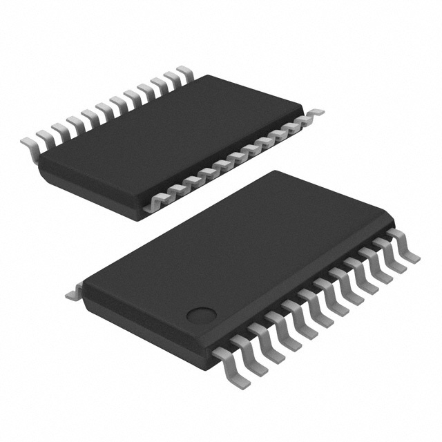
Package: TSSOP (Thin Shrink Small Outline Package)
Essence: Clock generation and distribution
Packaging/Quantity: Tape and Reel, 2500 units per reel
Specifications and Parameters
- Supply Voltage: 2.3V to 3.6V
- Operating Temperature Range: -40°C to +85°C
- Output Frequency Range: 1MHz to 200MHz
- Output Skew: ≤ 100ps
- Jitter: ≤ 50ps RMS
- Input Clock Frequency Range: 1MHz to 200MHz
- Output Logic Levels: LVCMOS
Pin Configuration
The CDCVF310PWRG4 has a total of 20 pins. The pin configuration is as follows:
- VDDA
- GND
- CLKIN
- CLKOUT0
- CLKOUT1
- CLKOUT2
- CLKOUT3
- CLKOUT4
- CLKOUT5
- CLKOUT6
- CLKOUT7
- CLKOUT8
- CLKOUT9
- CLKOUT10
- CLKOUT11
- CLKOUT12
- CLKOUT13
- CLKOUT14
- CLKOUT15
- VDDD
Functional Characteristics
The CDCVF310PWRG4 is designed to generate and distribute high-quality clock signals with low skew and low jitter. It provides 16 differential output pairs and one single-ended output. The device supports various input clock frequencies and offers flexible output frequency options.
Advantages and Disadvantages
Advantages: - High-performance clock generation - Low skew and low jitter - Wide operating temperature range - Flexible output frequency options
Disadvantages: - Limited number of output channels - Requires external power supply
Applicable Range of Products
The CDCVF310PWRG4 is suitable for applications that require high-quality clock signals with low skew and low jitter. It can be used in various electronic devices, including communication equipment, data storage systems, and digital signal processing applications.
Working Principles
The CDCVF310PWRG4 utilizes advanced clock generation techniques to produce stable and accurate clock signals. It incorporates PLL (Phase-Locked Loop) technology to synchronize the output clocks with the input reference clock. The device also includes internal dividers and multiplexers to provide flexible output frequency options.
Detailed Application Field Plans
- Communication Equipment: The CDCVF310PWRG4 can be used in routers, switches, and network interface cards to generate and distribute clock signals for data transmission and synchronization.
- Data Storage Systems: The device is suitable for use in hard disk drives, solid-state drives, and RAID controllers to ensure precise timing for data read and write operations.
- Digital Signal Processing: The CDCVF310PWRG4 can be employed in audio and video processing systems, as well as in radar and sonar applications, to maintain accurate timing for signal processing tasks.
Detailed Alternative Models
- CDCVF310PWR: Similar to CDCVF310PWRG4 but without RoHS compliance.
- CDCVF310PW: Same functionality as CDCVF310PWRG4 but in a different package (TSSOP-20).
5 Common Technical Questions and Answers
Q: What is the maximum output frequency of the CDCVF310PWRG4? A: The CDCVF310PWRG4 supports output frequencies up to 200MHz.
Q: Can the CDCVF310PWRG4 operate with a supply voltage below 2.3V? A: No, the CDCVF310PWRG4 requires a supply voltage between 2.3V and 3.6V for proper operation.
Q: Does the CDCVF310PWRG4 support LVDS (Low-Voltage Differential Signaling) outputs? A: No, the CDCVF310PWRG4 only provides LVCMOS (Low-Voltage Complementary Metal-Oxide-Semiconductor) outputs.
Q: What is the typical jitter performance of the CDCVF310PWRG4? A: The CDCVF310PWRG4 has a typical jitter of ≤ 50ps RMS.
Q: Can the CDCVF310PWRG4 be used in automotive applications? A: No, the CDCVF310PWRG4 is not designed for automotive use and does not meet the required automotive standards.
This concludes the encyclopedia entry for the CDCVF310PWRG4 clock generator integrated