

CY74FCT16373ATVRE4
Product Overview
Category
The CY74FCT16373ATVRE4 belongs to the category of integrated circuits (ICs).
Use
This IC is commonly used in digital systems for data storage and transfer applications.
Characteristics
- High-speed operation
- Low power consumption
- Wide operating voltage range
- Robust design for reliable performance
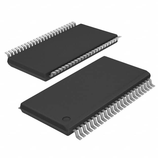
Package
The CY74FCT16373ATVRE4 is available in a small outline integrated circuit (SOIC) package.
Essence
This IC is essential for facilitating efficient data storage and transfer within digital systems.
Packaging/Quantity
The CY74FCT16373ATVRE4 is typically packaged in reels, with a quantity of 2500 units per reel.
Specifications
- Number of bits: 16
- Logic family: FCT
- Output type: Tri-state
- Operating voltage range: 4.5V to 5.5V
- Operating temperature range: -40°C to +85°C
- Input/output compatibility: TTL
Detailed Pin Configuration
The CY74FCT16373ATVRE4 has a total of 48 pins, which are arranged as follows:
- Pin 1: Output Enable (OE)
- Pin 2: Data Input D0
- Pin 3: Data Input D1
- Pin 4: Data Input D2
- Pin 5: Data Input D3
- Pin 6: Data Input D4
- Pin 7: Data Input D5
- Pin 8: Data Input D6
- Pin 9: Data Input D7
- Pin 10: Data Input D8
- Pin 11: Data Input D9
- Pin 12: Data Input D10
- Pin 13: Data Input D11
- Pin 14: Data Input D12
- Pin 15: Data Input D13
- Pin 16: Data Input D14
- Pin 17: Data Input D15
- Pin 18: Clock (CLK)
- Pin 19: Output Q0
- Pin 20: Output Q1
- Pin 21: Output Q2
- Pin 22: Output Q3
- Pin 23: Output Q4
- Pin 24: Output Q5
- Pin 25: Output Q6
- Pin 26: Output Q7
- Pin 27: Output Q8
- Pin 28: Output Q9
- Pin 29: Output Q10
- Pin 30: Output Q11
- Pin 31: Output Q12
- Pin 32: Output Q13
- Pin 33: Output Q14
- Pin 34: Output Q15
- Pin 35: Output Enable (OE)
- Pin 36: GND (Ground)
- Pin 37: VCC (Power Supply)
- Pin 38: Data Input D15
- Pin 39: Data Input D14
- Pin 40: Data Input D13
- Pin 41: Data Input D12
- Pin 42: Data Input D11
- Pin 43: Data Input D10
- Pin 44: Data Input D9
- Pin 45: Data Input D8
- Pin 46: Data Input D7
- Pin 47: Data Input D6
- Pin 48: Data Input D5
Functional Features
- High-speed data storage and transfer
- Tri-state outputs for bus-oriented applications
- Wide operating voltage range allows compatibility with various systems
- Robust design ensures reliable performance in demanding environments
Advantages and Disadvantages
Advantages
- High-speed operation enables efficient data processing
- Low power consumption helps conserve energy
- Wide operating voltage range enhances compatibility
- Tri-state outputs facilitate bus-oriented applications
Disadvantages
- Limited number of bits (16) may not be suitable for certain applications requiring larger data storage capacity
- Temperature limitations (-40°C to +85°C) restrict usage in extreme temperature conditions
Working Principles
The CY74FCT16373ATVRE4 operates based on the principles of digital logic. It utilizes flip-flops to store and transfer data, controlled by clock signals. The tri-state outputs allow multiple devices to share a common bus, enabling efficient data communication.
Detailed Application Field Plans
The CY74FCT16373ATVRE4 finds applications in various digital systems, including but not limited to: - Microprocessors - Data communication systems -
Senaraikan 10 soalan dan jawapan biasa yang berkaitan dengan aplikasi CY74FCT16373ATVRE4 dalam penyelesaian teknikal
Sure! Here are 10 common questions and answers related to the application of CY74FCT16373ATVRE4 in technical solutions:
Q: What is the CY74FCT16373ATVRE4? A: The CY74FCT16373ATVRE4 is a 16-bit transparent latch with 3-state outputs, designed for high-speed applications.
Q: What is the maximum operating frequency of the CY74FCT16373ATVRE4? A: The maximum operating frequency of the CY74FCT16373ATVRE4 is typically around 250 MHz.
Q: What is the voltage supply range for this device? A: The voltage supply range for the CY74FCT16373ATVRE4 is typically between 4.5V and 5.5V.
Q: Can I use this latch for level shifting applications? A: Yes, the CY74FCT16373ATVRE4 can be used for level shifting as it supports both TTL and CMOS logic levels.
Q: How many latch outputs does this device have? A: The CY74FCT16373ATVRE4 has 16 latch outputs, each capable of driving up to 24 mA.
Q: Does this latch have any built-in protection features? A: Yes, the CY74FCT16373ATVRE4 has built-in ESD protection on all inputs and outputs.
Q: Can I cascade multiple CY74FCT16373ATVRE4 devices together? A: Yes, you can cascade multiple CY74FCT16373ATVRE4 devices together to increase the number of latch outputs.
Q: What is the typical propagation delay of this latch? A: The typical propagation delay of the CY74FCT16373ATVRE4 is around 3.5 ns.
Q: Can I use this latch in high-speed data transfer applications? A: Yes, the CY74FCT16373ATVRE4 is suitable for high-speed data transfer applications due to its low propagation delay and high operating frequency.
Q: Is there a recommended PCB layout for using this device? A: Yes, the datasheet for the CY74FCT16373ATVRE4 provides a recommended PCB layout that should be followed for optimal performance.
Please note that these answers are general and may vary depending on specific application requirements. It is always recommended to refer to the device datasheet for accurate and detailed information.