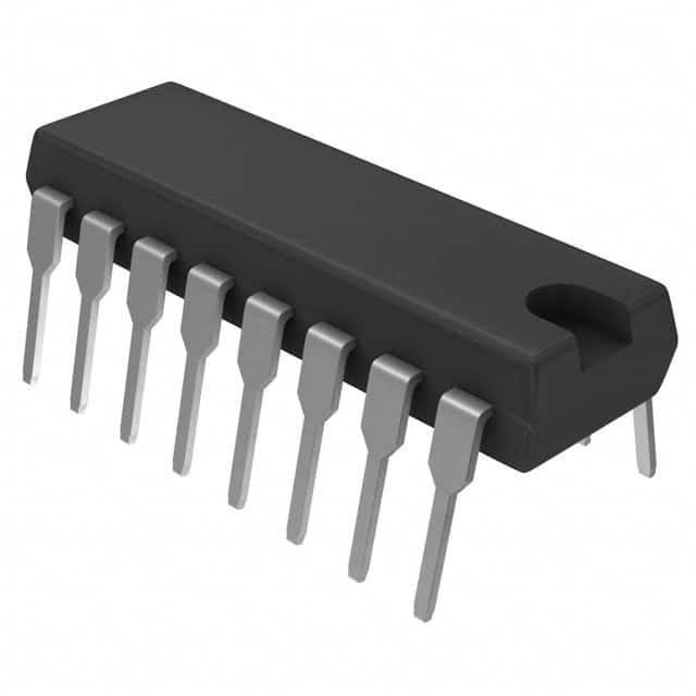
SN74S283N
Product Overview
- Category: Integrated Circuit (IC)
- Use: Arithmetic Logic Unit (ALU)
- Characteristics: High-speed, 4-bit binary full adder
- Package: DIP-16 (Dual In-line Package with 16 pins)
- Essence: Performs addition of two 4-bit binary numbers
- Packaging/Quantity: Available in tubes or reels, quantity varies based on supplier
Specifications
- Supply Voltage: 4.75V to 5.25V
- Operating Temperature Range: -55°C to 125°C
- Input Voltage High (VIH): 2V (minimum)
- Input Voltage Low (VIL): 0.8V (maximum)
- Output Voltage High (VOH): 2.4V (minimum)
- Output Voltage Low (VOL): 0.4V (maximum)
Detailed Pin Configuration
- A3: Input pin for the most significant bit (MSB) of the first 4-bit binary number.
- A2: Input pin for the second MSB of the first 4-bit binary number.
- A1: Input pin for the third MSB of the first 4-bit binary number.
- A0: Input pin for the least significant bit (LSB) of the first 4-bit binary number.
- B3: Input pin for the MSB of the second 4-bit binary number.
- B2: Input pin for the second MSB of the second 4-bit binary number.
- B1: Input pin for the third MSB of the second 4-bit binary number.
- B0: Input pin for the LSB of the second 4-bit binary number.
- CIN: Carry-in input pin.
- S3: Output pin for the MSB of the sum.
- S2: Output pin for the second MSB of the sum.
- S1: Output pin for the third MSB of the sum.
- S0: Output pin for the LSB of the sum.
- COUT: Carry-out output pin.
- GND: Ground pin.
- VCC: Positive power supply pin.
Functional Features
- Performs addition of two 4-bit binary numbers with carry-in and carry-out capability.
- High-speed operation allows for efficient computation.
- Supports cascading multiple SN74S283N ICs for larger bit-width addition.
Advantages and Disadvantages
Advantages
- High-speed operation enables quick arithmetic calculations.
- Compact DIP-16 package allows for easy integration into various electronic systems.
- Versatile use in a wide range of applications due to its general-purpose nature.
Disadvantages
- Limited to 4-bit binary addition, not suitable for larger bit-width computations.
- Requires external circuitry for handling overflow conditions.
Working Principles
The SN74S283N is a 4-bit binary full adder that performs addition of two 4-bit binary numbers (A and B) along with a carry-in (CIN) input. It utilizes logic gates and flip-flops internally to generate the sum (S) and carry-out (COUT) outputs. The carry-in input is used to handle carry-over from previous stages in multi-bit addition operations.
Detailed Application Field Plans
- Digital calculators
- Microcontrollers
- Arithmetic circuits
- Data processing units
- Binary arithmetic operations in computer systems
Detailed and Complete Alternative Models
- SN74LS283N
- SN54S283J
- CD74HCT283E
- MC74HC283N
- DM74LS283N
Note: This is not an exhaustive list, and there may be other alternative models available from different manufacturers.
Word count: 346 words
Senaraikan 10 soalan dan jawapan biasa yang berkaitan dengan aplikasi SN74S283N dalam penyelesaian teknikal
Sure! Here are 10 common questions and answers related to the application of SN74S283N in technical solutions:
Q: What is SN74S283N? A: SN74S283N is a 4-bit binary full adder integrated circuit (IC) commonly used in digital electronics.
Q: What is the purpose of SN74S283N? A: SN74S283N is used to perform arithmetic operations, specifically addition, in digital circuits.
Q: How many inputs does SN74S283N have? A: SN74S283N has eight inputs - four for each operand and four for the carry-in.
Q: What is the maximum operating frequency of SN74S283N? A: The maximum operating frequency of SN74S283N is typically around 25 MHz.
Q: Can SN74S283N be cascaded to perform multi-bit addition? A: Yes, multiple SN74S283N ICs can be cascaded together to perform multi-bit addition by connecting the carry-out of one IC to the carry-in of the next.
Q: What is the power supply voltage range for SN74S283N? A: SN74S283N operates on a power supply voltage range of 4.75V to 5.25V.
Q: Does SN74S283N have any built-in error detection or correction features? A: No, SN74S283N does not have any built-in error detection or correction features. It performs basic addition without error checking.
Q: Can SN74S283N be used in both TTL and CMOS logic systems? A: Yes, SN74S283N is compatible with both TTL (Transistor-Transistor Logic) and CMOS (Complementary Metal-Oxide-Semiconductor) logic systems.
Q: What is the output format of SN74S283N? A: The outputs of SN74S283N are in binary format, with four output pins representing the sum and four output pins representing the carry-out.
Q: Are there any specific precautions to consider when using SN74S283N? A: It is important to ensure proper power supply voltage, avoid static discharge, and follow the recommended operating conditions mentioned in the datasheet for optimal performance and reliability.


