

P6KE170A-E3/54
Product Overview
Category
The P6KE170A-E3/54 belongs to the category of transient voltage suppressor diodes.
Use
It is used for protecting sensitive electronic components from voltage transients induced by lightning, inductive load switching, and electrostatic discharge.
Characteristics
- Fast response time
- Low clamping voltage
- High surge current capability
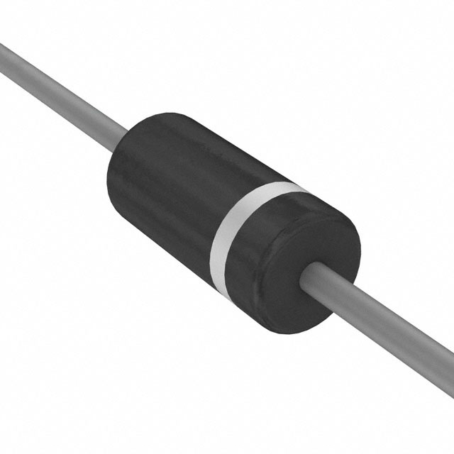
Package
The P6KE170A-E3/54 is typically available in a DO-15 package.
Essence
The essence of the P6KE170A-E3/54 lies in its ability to divert excessive current away from sensitive components, thereby safeguarding them from damage.
Packaging/Quantity
It is commonly packaged in reels or tubes, with quantities varying based on manufacturer specifications.
Specifications
- Peak Pulse Power: 600W
- Breakdown Voltage: 170V
- Maximum Clamping Voltage: 275V
- Operating Temperature Range: -55°C to +175°C
Detailed Pin Configuration
The P6KE170A-E3/54 typically has two pins, with no specific pin configuration as it is a unidirectional TVS diode.
Functional Features
- Bi-directional clamping capability
- Low incremental surge resistance
- High temperature stability
Advantages
- Provides effective protection against voltage transients
- Fast response time ensures minimal impact on the protected circuit
- Wide operating temperature range allows for versatile application
Disadvantages
- May require additional circuitry for comprehensive transient protection
- Limited to unidirectional clamping
Working Principles
When a voltage transient occurs, the P6KE170A-E3/54 conducts and diverts excess current away from the protected circuit, limiting the voltage across it to a safe level.
Detailed Application Field Plans
The P6KE170A-E3/54 is commonly used in: - Power supplies - Telecommunication equipment - Automotive electronics - Industrial control systems
Detailed and Complete Alternative Models
- P6KE6.8A-E3/54
- P6KE10A-E3/54
- P6KE15A-E3/54
- P6KE200A-E3/54
In conclusion, the P6KE170A-E3/54 transient voltage suppressor diode offers reliable protection against voltage transients, making it an essential component in various electronic applications.
Word Count: 324
Senaraikan 10 soalan dan jawapan biasa yang berkaitan dengan aplikasi P6KE170A-E3/54 dalam penyelesaian teknikal
What is the P6KE170A-E3/54?
- The P6KE170A-E3/54 is a 600W TVS (transient voltage suppressor) diode designed to protect sensitive electronics from voltage spikes and transients.
What is the maximum clamping voltage of the P6KE170A-E3/54?
- The maximum clamping voltage of the P6KE170A-E3/54 is 275V at 5.0A.
What are the typical applications for the P6KE170A-E3/54?
- The P6KE170A-E3/54 is commonly used in surge protection, overvoltage protection, and transient voltage suppression in various electronic circuits and systems.
What is the breakdown voltage of the P6KE170A-E3/54?
- The breakdown voltage of the P6KE170A-E3/54 is 170V.
What is the peak pulse power dissipation of the P6KE170A-E3/54?
- The peak pulse power dissipation of the P6KE170A-E3/54 is 600W.
What is the operating temperature range of the P6KE170A-E3/54?
- The P6KE170A-E3/54 has an operating temperature range of -55°C to +175°C.
Is the P6KE170A-E3/54 RoHS compliant?
- Yes, the P6KE170A-E3/54 is RoHS compliant, making it suitable for use in environmentally conscious designs.
Can the P6KE170A-E3/54 be used for ESD (electrostatic discharge) protection?
- Yes, the P6KE170A-E3/54 can be used for ESD protection in electronic circuits and systems.
What is the package type of the P6KE170A-E3/54?
- The P6KE170A-E3/54 is available in a DO-15 package, which is a popular axial leaded package for diodes.
What are some best practices for incorporating the P6KE170A-E3/54 into a circuit design?
- It is recommended to place the P6KE170A-E3/54 as close as possible to the input or output terminals of the circuit to maximize its protective effect. Additionally, proper PCB layout and grounding techniques should be employed to optimize its performance.