

IRFI9540GPBF
Product Overview
Category
The IRFI9540GPBF belongs to the category of power MOSFETs.
Use
It is commonly used in electronic circuits for switching and amplification applications.
Characteristics
- High voltage capability
- Low on-resistance
- Fast switching speed
- Low gate drive power
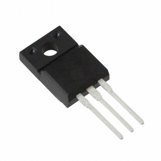
Package
The IRFI9540GPBF comes in a TO-220AB package.
Essence
This power MOSFET is essential for controlling high-power loads in various electronic devices and systems.
Packaging/Quantity
The IRFI9540GPBF is typically packaged in reels or tubes, with quantities varying based on manufacturer specifications.
Specifications
- Drain-Source Voltage (Vdss): 100V
- Continuous Drain Current (Id): 19A
- RDS(ON) (Max) @ VGS = 10V: 0.117Ω
- Gate-Source Voltage (Vgs): ±20V
- Power Dissipation (Pd): 75W
Detailed Pin Configuration
The IRFI9540GPBF features a standard TO-220AB pin configuration: 1. Gate (G) 2. Drain (D) 3. Source (S)
Functional Features
- High input impedance
- Low input capacitance
- Enhanced 30V VGS rating
- Avalanche energy specified
Advantages
- Suitable for high-frequency applications
- Low conduction losses
- Robust and reliable performance
- Compatible with various driving circuits
Disadvantages
- Higher cost compared to some alternative models
- Sensitive to electrostatic discharge (ESD)
Working Principles
The IRFI9540GPBF operates based on the principles of field-effect transistors, utilizing the control of an electric field to modulate the conductivity of the device.
Detailed Application Field Plans
The IRFI9540GPBF is widely used in: - Switching power supplies - Motor control circuits - Audio amplifiers - LED lighting systems - DC-DC converters
Detailed and Complete Alternative Models
Some alternative models to the IRFI9540GPBF include: - IRF9540N - FQP19N20C - STP19NF20
In conclusion, the IRFI9540GPBF power MOSFET offers high-performance characteristics suitable for a wide range of electronic applications, making it a valuable component in modern electronic design and manufacturing.
[Word count: 309]
Senaraikan 10 soalan dan jawapan biasa yang berkaitan dengan aplikasi IRFI9540GPBF dalam penyelesaian teknikal
What is the IRFI9540GPBF?
- The IRFI9540GPBF is a power MOSFET designed for high-speed switching applications in power supplies, converters, and motor control systems.
What is the maximum drain-source voltage of the IRFI9540GPBF?
- The maximum drain-source voltage of the IRFI9540GPBF is 100V.
What is the continuous drain current rating of the IRFI9540GPBF?
- The continuous drain current rating of the IRFI9540GPBF is 23A.
What are the typical applications of the IRFI9540GPBF?
- Typical applications of the IRFI9540GPBF include power supplies, DC-DC converters, motor control, and high-frequency inverters.
What is the on-state resistance (RDS(on)) of the IRFI9540GPBF?
- The on-state resistance of the IRFI9540GPBF is typically around 0.117 ohms.
What is the gate-source voltage (VGS) required to fully enhance the IRFI9540GPBF?
- The gate-source voltage required to fully enhance the IRFI9540GPBF is typically around 10V.
Is the IRFI9540GPBF suitable for high-frequency switching applications?
- Yes, the IRFI9540GPBF is suitable for high-frequency switching due to its fast switching characteristics.
Does the IRFI9540GPBF require a heatsink for operation?
- It is recommended to use a heatsink with the IRFI9540GPBF, especially when operating at high currents or in high ambient temperatures.
What are the thermal characteristics of the IRFI9540GPBF?
- The IRFI9540GPBF has a low thermal resistance and is capable of dissipating heat effectively when properly mounted on a heatsink.
Are there any important considerations for driving the IRFI9540GPBF in a circuit?
- It's important to ensure proper gate drive voltage and current to fully enhance the IRFI9540GPBF and minimize switching losses. Additionally, attention should be paid to minimizing inductive voltage spikes during switching.